


Description
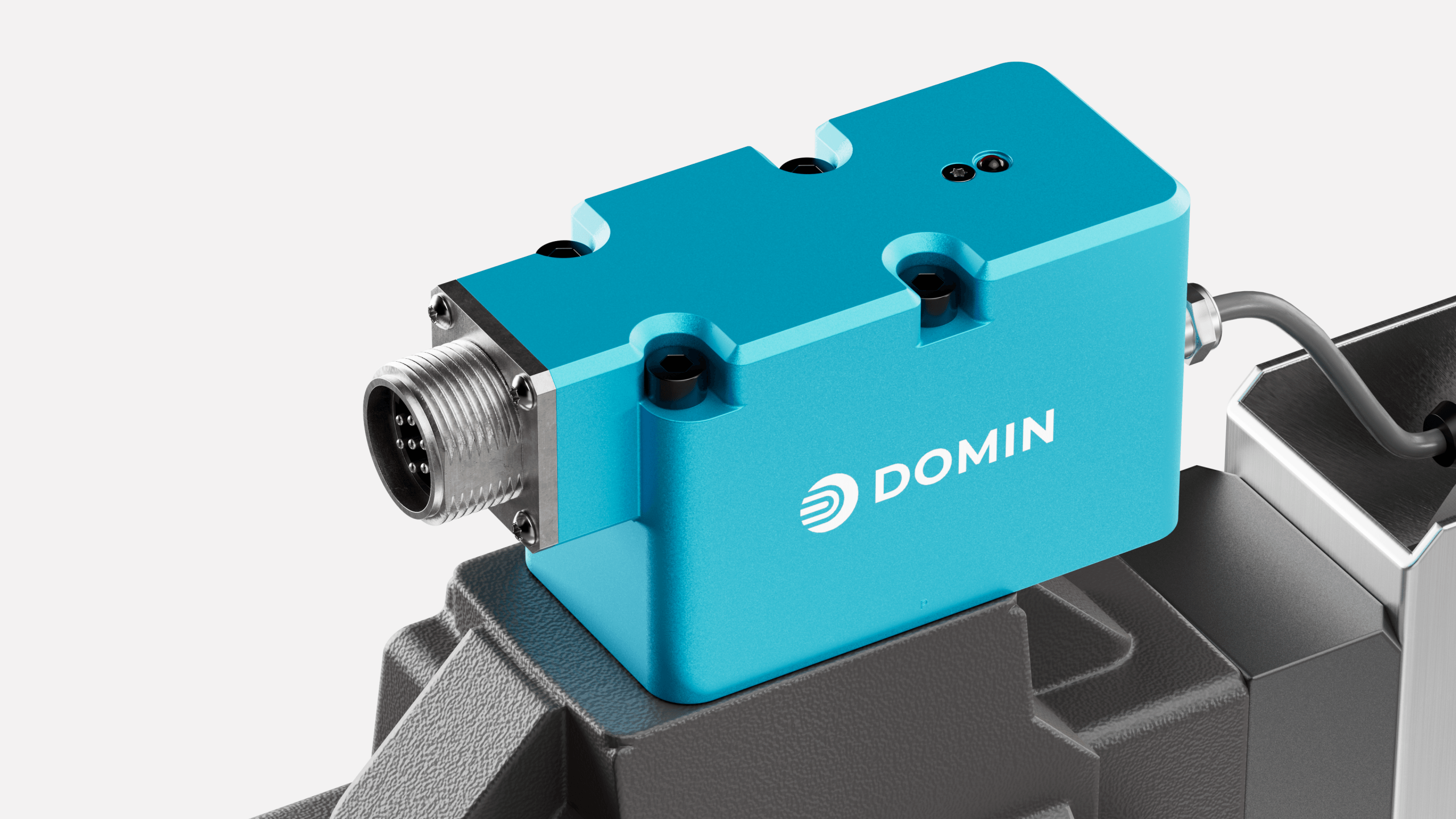
The Domin S12 Pro is a high-performance, two-stage servo valve in NG16 size, designed for applications where precision and stability have a direct impact on safety, throughput and operating costs. Built on proven Domin valve technology as the pilot stage, the S12 Pro delivers stable, responsive control across the entire operating range and maintains its integrity even under the most demanding conditions. This makes it ideal for systems where instability cannot be tolerated – such as highly dynamic presses, test benches, steel and rolling mill drives, injection moulding machines with high repeatability requirements, and heavy-duty industrial automation with high flow rate demands.
Technical highlights
- Highly dynamic two-stage servo valve with direct-drive pilot control, size NG16
- Integrated on-board electronics with slide position feedback – no external amplifier required
- Response time less than 6.5 ms, frequency response above 130 Hz (–3 dB gain) and above 100 Hz (–90° phase, ±25 per cent signal)
- Hysteresis less than 0.2 per cent, threshold less than 0.1 per cent, zero-point drift less than 1 per cent
- Nominal flow rate 250 to 580 l/min (rated at 35 bar ΔP per control edge), maximum flow rate up to 1000 l/min
- Maximum operating pressure 350 bar (P, A, B, X) / 250 bar (Y, T)
- Pilot valve leakage less than 0.8 l/min, main stage leakage less than 1.0 l/min (at 100 bar)
- Power consumption less than 5 W, supply voltage 22–30 V DC, peak current 4.5 A
- Vibration resistance 10 g, shock resistance 15 g, protection rating IP65
- Weight under 7 kg, mounting interface ISO 4401-07-07 (ports enlarged to 20 mm), tightening torque 40 Nm (M10) or 8 Nm (M6)
Order code: S12 Pro – [1] – [2] – [3] – [4] – [5] – [6] – [7] – [8] – [Custom ID]
Example: S12 Pro – 400 – A – A – C – E – N – R – N
= 400 l/min · Axis (linearised) · ±10 V · Passive centre position · 6+PE circular connector · no enable · standard oil · nitrile
| Position | Description | Options |
|---|---|---|
| [1] | Nominal flow rate | 250 to 580 l/min (any value, rated at 35 bar ΔP per control edge) – suffix R for reversed A/B connections (e.g. 580R) |
| [2] | Valve overlap & flow characteristic curve | A – Axis (1 per cent overlap, standard flow map: linear, 100 per cent gain across the entire range) B – Float (5 per cent over-coverage P, 5 per cent under-coverage T, standard flow map: deadband) D – Blocked (5 per cent overlap, all ports blocked at the zero point, default flow map: deadband) X – Special version available on request Optionally, a second code can specify a different flow map: A – Linear, D – Deadband (0% gain within the ±10% range), O – Gradual (50% gain within the ±3% range). Example: AD = Axis slide valve with deadband characteristic curve. |
| [3] | Control signal (I/O) | A – ±10 V (input impedance 200 kΩ, output ±10.5 V) B – ±20 mA (input impedance 402 Ω, output ±21 mA, load impedance 600 Ω) C – 4 – 20 mA (402 Ω, output 3.8 – 21 mA; input < 2 mA deactivates the motor drive) F – ±10 mA (402 Ω, output ±10.5 mA) G – ±50 mA (200 Ω, input only; standard output as per Mode A) X – Special version available on request |
| [4] | Power-off position (power-off behaviour) | A – Axis (leakage flow across all control edges) B – Float (P blocked, A, B and T connected) C – Passive (the spool returns passively to the centre position under typical flow conditions) D – Blocked (all ports blocked) PA – A Bias (P connected to A, B connected to T) PB – B Bias (P connected to B, A connected to T) X – Special version available on request |
| [5] | Electrical connector | E – 6+PE circular connector, EN 175201-804 / MIL 5015, housing size 14 (A = +24 V / B = 0 V / C = 0 V reference or enable output / D = input+ / E = input− / F = output signal / G = earth) E4 – 4-pin round plug, EN 175201-804 / MIL 5015, housing size 14 (A = +24 V / B = Input+ / C = Input− / D = 0 V) X – Special version available on request |
| [6] | Enable function | N – No enable function Y – Enable mode via voltage input (Drive ON: 9–30 V / Drive OFF: 0–5 V / input impedance typ. 15 kΩ; available only with connector E) X – Special version available on request |
| [7] | Hydraulic fluid | R – Hydraulic oil in accordance with DIN 51524, filtered to ISO 4406 18/16/13 (water-free synthetic fluids available on request) X – Special version available on request |
| [8] | Sealing material | N – Nitrile NBR (Shore 90) – standard for mineral oils V – Viton FKM (Shore 85) – increased resistance to high temperatures and chemicals X – Special version available on request |
Data sheet: https://domin.com/datasheet/s12-pro