


Description
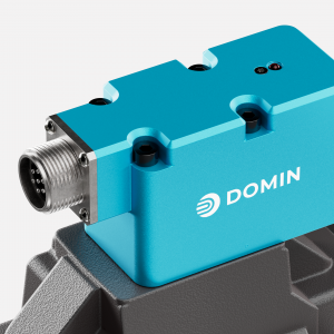
The Domin P12 Pro is a two-stage servo-proportional valve with a nominal size of NG16, which utilises the P6 Pro as a directly driven pilot stage. With a nominal flow rate of up to 580 l/min, it delivers industrial performance without the complexity of conventional servo valves – whilst offering a compact design, low weight and high robustness for continuous operation. Compatibility with standardised NG16 interfaces simplifies commissioning and ensures stable long-term performance as well as reduced maintenance requirements. The P12 Pro is designed for industrial production facilities where stable, repeatable control and predictable life-cycle costs are paramount.
Technical highlights
- Two-stage servo valve with directly driven pilot stage (P6 Pro), nominal size NG16
- Integrated on-board electronics with slide position feedback
- Response time under 12 ms, frequency response above 60 Hz (–3 dB and –90° phase, at 210 bar pilot pressure)
- Hysteresis less than 0.2 per cent, threshold less than 0.1 per cent, zero-point offset less than 1 per cent
- Maximum operating pressure: 350 bar at P, A, B, X – 250 bar at Y, T
- Nominal flow rate up to 580 l/min (rated at 35 bar ΔP per control edge), maximum 1,000 l/min
- Power consumption less than 5 W, supply voltage 22–30 V DC
- IP65 protection rating, weight under 7 kg
- Vibration resistance 10 g, shock resistance 15 g
- Choice of two seal materials: nitrile, Viton
- Mounting interface ISO 4401-07-07 (connections enlarged to 20 mm), fastenings: M10 × 50 mm (40 Nm) and M6 × 50 mm (8 Nm)
Order code: P12 Pro – [1] – [2] – [3] – [4] – [5] – [6] – [7] – [8] – [Custom ID]
Example: P12 Pro – 580 – A – A – C – E – N – R – N
= 580 l/min · Axis · ±10 V · Passive (centre position) · 6+PE round plug · no enable · standard oil · nitrile
| Position | Description | Options |
|---|---|---|
| [1] | Nominal flow rate | 160 to 580 l/min (any value, rated at 35 bar ΔP per control edge) – suffix ‘R’ for reversed A/B connections (e.g. 580R) |
| [2] | Flow behaviour | A – Axis (1 % overlap, linear characteristic curve) B – Float (5 % overlap at P, 5 % under-travel at T, deadband characteristic curve) D – Blocked (5 % overlap, deadband characteristic curve: no flow between ±10 % of setpoint) X – Special version on request Alternative characteristic curves available via a second letter: A – linear, D – deadband, O – gradual (50 per cent gain between ±3 per cent of setpoint), e.g. AD = Axis with deadband characteristic curve |
| [3] | Control signal | A – ±10 V | B – ±20 mA | C – 4–20 mA | F – ±10 mA | G – ±50 mA (input only, output ±10 V) | X – Special |
| [4] | Power-off position | A – Axis (leakage flow across all control edges) B – Float (P blocked, A, B and T connected) C – Passive (spool returns passively to the centre position under typical flow conditions) D – Blocked (all ports blocked) PA – A pre-set (P connected to A, B connected to T) PB – B pre-set (P connected to B, A connected to T) X – Special version on request This position is assumed in the event of a power failure, fault or when the enable input is deactivated. |
| [5] | Electrical connector | E – 6+PE circular connector, EN 175201-804 / MIL 5015, housing size 14 E4 – 4-pin circular connector, EN 175201-804 / MIL 5015, housing size 14 |
| [6] | Enable function | N – No enable function Y – Enable mode via voltage input (Drive ON: 9–30 V / Drive OFF: 0–5 V; only with connector E) X – Special version available on request |
| [7] | Hydraulic fluid | R – Hydraulic oil in accordance with DIN 51524, filtered to ISO 4406 18/16/13 (water-free synthetic fluids available on request) X – Special version available on request |
| [8] | Sealing material | N – Nitrile NBR (Shore 90) – standard for mineral oils V – Viton FKM (Shore 85) – increased resistance to high temperatures and chemicals X – Special version available on request |
Data sheet: https://domin.com/datasheet/p12-pro